Pro2 PLUS Receiver
Overview
The WeatherDuino Pro2 PLUS was released in 2017 as the successor to the Pro2 receiver.
The Pro2 PLUS uses an ATMEL AT Mega 2560 microcontroller with 256K of RAM and 8K of SRAM. Compared to its predecessor, the larger memory size and the enhanced hardware allowed us to add several new features and functions, including:
- Touch-sensitive color TFT display
- WiFi capability (amongst other things, this allows direct upload to WU without the need to have a connection to a PC or Raspberry Pi - Stand alone Mode).
- Sync system time with NTP servers
- Mini Web Server - allows monitoring real time weather data from anywhere on your local network.
- 2 GPIO ports plus 1 GPO port (can drive a relay up to 50mA) which can be used to control external devices, such as heaters, watering systems, etc.
- Davis VP2 emulation was enhanced with support for the LOOP2 command.
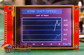
- Graphs of the last 12 hours for the most important weather variables (Atmospheric pressure, Wind Gust and Speed, Rain, Outside Temperature and Humidity).
- Support for the WeatherDuino Air Quality Monitor (see below for a detailed section on this optional instrument).
- Internationalization - User can chose the interface language (Check here the list of currently available languages).
For a full comparison between WeatherDuino receivers, please see the (WeatherDuino Receivers - Comparison Chart)
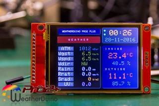
The addition of the Touch-sensitive Color display allows us to display the weather data organized in several screens. For example, data from all the seven extra sensors supported (Davis standard) can now be seen at once in the just one screen of data.
To navigate between all the data screens, just touch on one side of the screen. A touch on the right side advances to next data screen, a touch on the left side returns to the previous data screen. There are also other touch actions which will be described later.
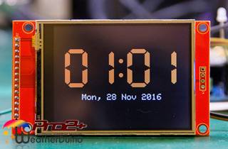
Pictures below illustrate some of the available data screens:
 |  |  |
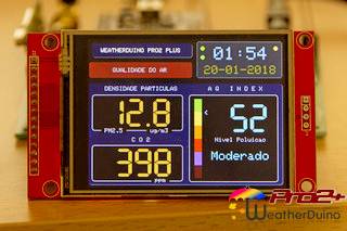 | 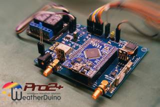 | 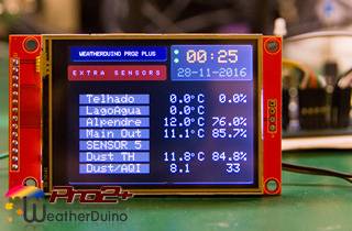 |
We take backward compatibility very seriously. Despite all the new features, the Pro2 PLUS can work with the same transmitters used in older receiver versions. This way, existing users can take advantage of the Pro2 PLUS by just upgrading the receiver, without having to change anything in the hardware of their existing transmitter units.
Notes on some of the Required Parts
The WeatherDuino Pro2 PLUS receiver is supplied as an almost fully assembled receiver, but still requires some specific parts to be added by the user.
A detailed parts list (includes information and pictures of all the specific parts), can be downloaded from here: WeatherDuino Pro2 PLUS - Parts List.
All parts can be easily found on several eBay sellers, or at local electronic parts store. Pay attention to the details shown in the photographs when you buy any of those parts.
Let's start with the microcontroller.
The Pro2 PLUS uses a Meduino Mega2560 Pro-mini board, a reduced size version of the traditional Arduino Mega 2560.
The best place (and perhaps the only one) to find and buy this board its on eBay. Do a search for 'Meduino mini Mega'.
This board is available in two versions, one with female double headers already soldered, and another supplied with male double headers not soldered. We recommend the last option. Why? Because if you intend to install the Meduino board in a socket (recommended) it makes more sense to install female sockets on the PCB, on the other hand if your prefer to solder the Meduino board directly to the PCB (not recommended) you have all you need as the male double pin headers are supplied together with the Meduino board.
A special note to Australian users: some sellers state they can ship the Meduino board from Australia, allowing for a quick delivery, however always compare the price against the Hong Kong shipping alternative.
Now the TFT display.
The WeatherDuino Pro2 PLUS receiver only works with the model and type of TFT display specified on the parts list. Pay particular attention when buying this part, since recently some variants of the supported model became available through some eBay sellers. Don't buy a model that is “almost like” the one pictured in the parts list. In particular, if the back side of the display board is different to that shown it probably will not be suitable.
Which Barometric and Temperature / Humidity sensors can be used?
As usual with WeatherDuino systems, there are several options.
Barometric sensors:
- BME280 (Bosch)
- BMP280 (Bosch)
- BMP180 (Bosch)
- BMP085 (Bosch older model, but still usable)
Temperature / Humidity sensors:
- SHT31 (Sensirion)
- SHT21 (Sensirion)
- HTU21D
The list above gives the generic name/version of the sensor. Generally those sensors are sold installed in small boards called modules, which are available from several sellers in several shapes and pinouts. Once again, pay attention to the models pictured on the WeatherDuino Pro2 PLUS - Parts List.
The Pro2 PLUS supports the BOSCH integrated environmental sensor BME280, which combines in just one unit, individual high linearity, high accuracy sensors for pressure, humidity and temperature.
It may make sense using just one module instead of two separated modules, one for barometric pressure and another for Temperature / Humidity. Just a hint, the choice its yours.
Radio Frequency modules
Last, but not least, lets talk about the Radio Frequency modules.
The Pro2 PLUS uses the same well-tested radio frequency modules used on the Pro2 system. All the radio frequency modules are available in 433Mhz and 315Mhz versions. The large majority of WeatherDuino users are using the 433Mhz version. The use of 433MHz RF radios for hobby projects is allowed in most countries around on the world, however for the rare cases where national regulations don't allow the use of the 433MHz frequency, you can use the 315MHz version of the same RF radio module. Performance is almost the same with a slightly advantage for 433MHz.
Be sure you get the correct RF radio modules so they will fit nicely on the PCB, once again refer to the pictures on the WeatherDuino Pro2 PLUS - Parts List.
You may also like to read these articles:
General Assembling Guide / Hints
As with any electronic circuit care should be taken during assembling. The Pro2 PLUS Receiver PCB has some static sensitive IC's, so please take the usual care when dealing with these kind of devices. If needed, please use Google for more information about this matter.
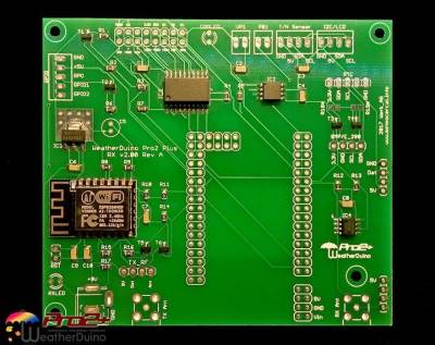
The Pro2 PLUS receiver is supplied with all the SMD parts already assembled, making it an almost finished system. To finish it, users just have to solder to the board some single and double pin headers, and a few connectors.
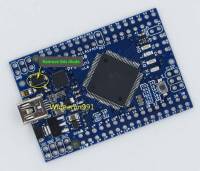 There is a very important procedure, that should always be done on the Meduino Mini Mega board before installing it onto the WeatherDuino Pro2 PLUS receiver board.
Always remove the diode illustrated on the picture on the right (Click to enlarge).
A failure to do this procedure may lead to permanent damage to the WeatherDuino Pro2 PLUS receiver in the event that the main power supply fails, and the board remains powered by the USB port only.
Removing the diode, ensures that the Receiver only gets power through the external power supply.
In general we use connectors and pin headers with a pin space of 2.54mm. There many types of connectors that fit on the pcb, use your preferred ones.
For the Meduino Mega Mini board we recommend installing female double header connectors on the pcb side.
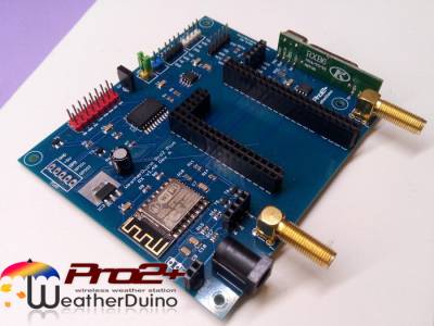
Once all the pin headers and connectors have been placed and soldered to the pcb, your Pro2 PLUS board will look similar to the picture below on the right.
Now that all pin headers and connectors are installed, its time to start with the connections.
The pinout of all connectors is clearly labelled on the board, so correctly connect any of the required parts. It's only a matter of paying attention to the labels on the board and the labels on each part being connected.
By experience we know that connecting the TFT display to the board is the operation which causes most problems. For this reason, we are including here a table with the pins correspondence between the Pro2 PLUS pcb and the TFT display.
| Connections - TFT Display | |
| TFT Display | Pro2 PLUS pcb |
|---|---|
| T-IRQ | T-IRQ |
| T-DO | T_MISO |
| T-DIN | T-MOSI |
| T-CS | T-CS |
| T-CLK | T-SCK |
| SDO(MISO) - Not used | |
| LED | LED+ |
| SCK | SCK |
| SDI(MOSI) | MOSI |
| D/C | DC |
| RESET | RST |
| CS | CS |
| GND | GND |
| VCC | VCC |
| 3.3V - Not used | |
The great moment is coming. It's almost time to apply power to the board and program it.
Before applying power to the Pro2 PLUS board, first measure the output voltage of your power supply. Make sure output voltage is in the range of 7.5V to 9V.
Powering the system with a voltage greater than 9V will make that the voltage regulators produce excessive heat.
Under normal working conditions the 3.3V voltage regulator runs just slightly warm, and moderately hot when the TFT backlight is turned on, but never very hot.
Installing and Configuring the software
If you are a newcomer to the system you should start by reading some general information about: Programming WeatherDuino devices, otherwise continue reading.
At this point we are assuming that you already have all the required libraries installed.
After loading the Pro2 PLUS software in Arduino IDE, the first thing that should always be done, is reviewing all user configurable options. Click on the 'Config_Option.h' tab, all user configurable options are here.

Here you will define things like your Station_ID, Time Zone, user interface language, and many other things. Review them all, and edit each one to suit your individual installation. Each user configurable option includes comments about their use and available options. Most options are self-explanatory.
After having finished reviewing and editing all the user configurable settings, click on the 'Credentials.h' tab. This is where credentials to access some services are stored. For example, if you have enabled the direct upload to Wunderground option, you need to provide your access details. Below you can see an example of a 'Credentials.h' file.
//
 --------------------------------------------------------------------------------------
//         WeatherDuino Pro2 PLUS RF Receiver v6.x
//               Personal Credentials File
//
 --------------------------------------------------------------------------------------
//
//
// --------------------------------------------------------------------------------------
//   WiFi Credentials
// --------------------------------------------------------------------------------------
#define WIFI_SSID        "My_WiFi_Station_ID"
#define WIFI_PASSWORD    "My_WiFi Password"

// --------------------------------------------------------------------------------------
//   WU Credentials
// --------------------------------------------------------------------------------------
#define WUNDERGROUND_STATION_ID "xxxxxxxxxx"           // WU Station ID
#define WUNDERGROUND_PWD        "xxxxxxxxxx"           // WU Station Key (It's more secure use Station Key than your WU account passw)
Now that the software is configured, save the changes and compile the code. If there aren't any compile errors (it should not have any) you are almost ready to upload the compiled code to the receiver microcontroller.
Do you remember having installed a PROGRAM / RUN switch? If so, it's time to use it!
Make sure that the switch is at PROGRAM position (switch open), and use the Arduino IDE to upload the code.
Initialization Sequence
The first time a new receiver runs, it needs to perform a special initialization sequence which will cause the receiver to automatically reboot. This is a normal (and desirable) behaviour.
This initialization sequence ends only after the receiver has received at least one data packet from each of the three main sensors (Temperature / Humidity, Wind and Rain).
In the middle of the initialization, screen, you will see three letters (TWR) that will change from Red to Green once the corresponding data packet is received.
From what is written above it's easy to conclude that if you don't have a Transmitter unit already working and transmitting data, the receiver will stay forever in the initialization sequence. This is why we recommend to anyone that is starting to build a WeatherDuino weather station, to always start by assembling the Transmitter unit first.
On subsequent restarts, the receiver will also remain in the initialization screen until it receives data from the three main sensors referred above.
Once the initialization sequence completes, you can start your preferred weather software.
Once communication is established the COM LED starts to blink, indicating active communication between the receiver and the weather software.
Before starting your preferred Weather Software, don't forget to put the PROGRAM / RUN switch in RUN position (switch closed).
A symptom that you have forgotten to put the switch in RUN position is a system reboot each time you attempt to start the weather software.
Configuring Weather Software
Depending on some of the user configurable options, and the type of weather instruments used in each particular case, some specific settings may have to be configured on the weather software.
For detailed information on how to configure Cumulus 1 or Cumulus MX, please refer to this article: Configuring Cumulus Software.
Upgrading the software
Having your receiver always running the latest software its very important. That ensures you that are always up-to-date with the latest features and getting the best performance.
The Pro2 PLUS receiver has the capability to inform you about the latest software version available. Navigate to the System Info data screen, there you can see not only the installed software version but also the latest software version available.
NOTE: For this function to work, the receiver should have the WiFi active.
Upgrading the software is a straightforward process that isn't much different than initial programming. Don't forget: any time you upgrade the software always revise and edit the user configurable options, as explained above.
Don't save some minutes now and risk hours of frustration later. Never copy / paste the Config_Options.h and Credentials.h file from a previous version to a new one, this can cause unforeseeable problems.
Here are the steps that we strongly recommend to be done on each software upgrade
- Before stopping / exiting your weather software (Cumulus or other), if used or active, disable the use of the data logger.
- Do a backup of your weather data.
- Change the PROGRAM / RUN switch to PROGRAM position.
- Upload the software to your receiver.
- Let it re-initialise, and then change the PROGRAM / RUN switch to RUN position.
- After the initialization sequence, check in the main data screen that the values shown are sensible (I'm just being caution).
- Start your weather software, communication with the receiver should start immediately.
- Enable the use of the data logger again in your weather software if you wish to use it.
Accessing the internal webpage
If the webserver is enabled in Config_Options, just open your browser and type the IP address of the receiver.
Navigating between data screens
All Weatherduino devices equipped with a 2.8“ TTF screen use the same navigational scheme.

User Interface - List of available languages
Currently, the user interface can be set to any of the following languages:
- Czech - Translation by Zdenek
- Dutch - Translation by Pierrelux
- English - Base Language
- French - Translation by Laulau
- German - Translation by engolling
- Italian - Translation by kraken1881
- Polish - Translation by jarekh3
- Portuguese - Translation by Werk_AG
- Spanish - Translation by Ardummy
Is your language not on the list?
Maybe you could contribute to the project with a translation. It will not take more than an hour of your time, and a whole country will thank you.
Custom Box for the WeatherDuino Pro2 PLUS receiver
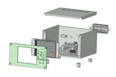
A member of the WeatherDuino Team (Jarek from Poland) has designed a custom case for the WeatherDuino Pro2 PLUS receiver.
Anyone with a 3D printer can print it at home, or order it through any of the several 3D print services available online.
The required files are freely available here: https://www.thingiverse.com/thing:3137127
If you don't have a 3D printer, you can order your case directly from online 3D printing services like 3Dhubs.
Where I can get the WeatherDuino Pro2 PLUS?
All information about prices, availability and how to order can be found here: WeatherDuino Pro2 PLUS, prices and availability.
WeatherDuino Pro2 PLUS Receiver - Air Quality Monitor
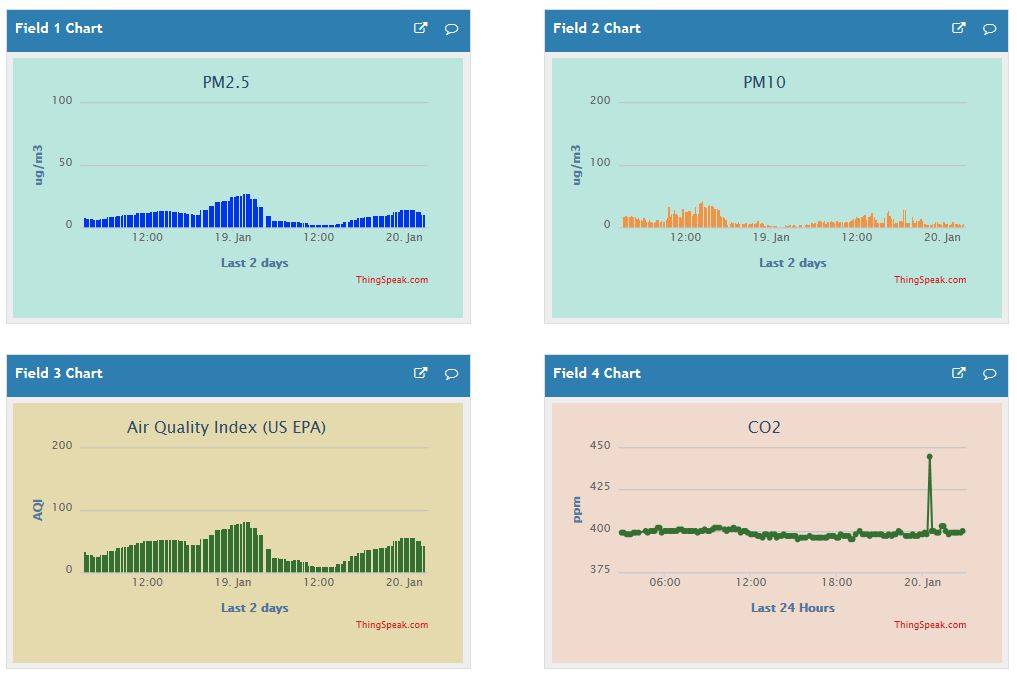
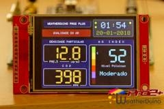 Since the WeatherDuino Pro2 PLUS was released at the beginning of 2017, there have been many developments in the software, which have increased its usability and functionality in many ways. One of those improvements was special: the WeatherDuinoAir Quality monitor. To take measurements of the air quality (PM2.5 and PM10), we have designed a totally new device known as Air Quality Monitor I(Click to see detailed information).
This kind of data is so new that currently no weather software processes them, so we have added three ways to allow users to make use of them outside of the WeatherDuino system.
Air Quality data can be sent to:
- A Thingspeak channel (See images below)
- Your own server to store in a SQL database
Both options can be used simultaneously, or in any combination. Usage is defined in the user configurable options.
Example of Air Quality graphs plotted on an Thingspeak channel, from data sent by an Pro2 PLUS weather station at each 10 minutes.
